Version 20.0 new features and enhancements
Recent developments in LUSAS have enhanced our ability to deliver a single advanced solution for any infrastructure project. LUSAS version 20.0 extends these capabilities even further, supports more design codes, and in summary includes:
New Software Option: Masonry Bridge Wizard
The new Masonry Bridge Wizard software option generates 2D or 3D continuum models of single and multi-span bridges, including piers and abutments, with or without a skew, using linear or nonlinear materials. Common features are grouped and named to allow for easy manipulation of the model, or selective viewing of results. Optional library-based train loading can be defined within the wizard. Road and rail traffic loading to supported design codes can be assigned from within Modeller.
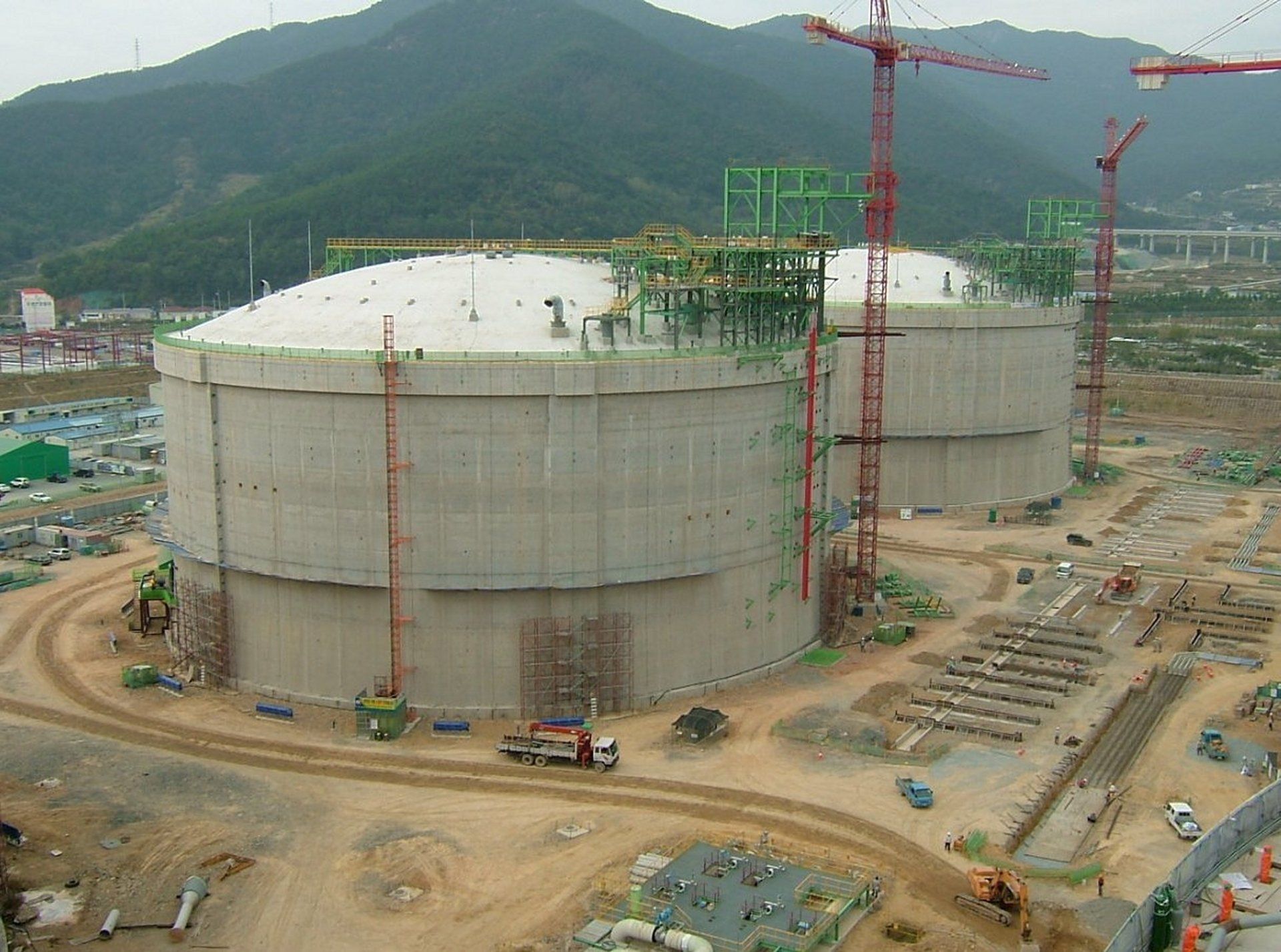
Updated LNG Tank System
Developments to the LNG tank system since Version 19.1 that are available for use when running the LNG Tank System in Version 20.0 include:
- Modelling of elevated tanks including isolator, pedestals, with raft and optionally piles.
- Automatic creation of piled foundations for above ground tanks
- Spillage (thermal) analysis.
- Wind loading to ASCE (USA) and GB50010 (China) codes.
- RC design to GB50009 (China)
- Comprehensive design check reports in spreadsheets.
- A range of pre-processing improvements.
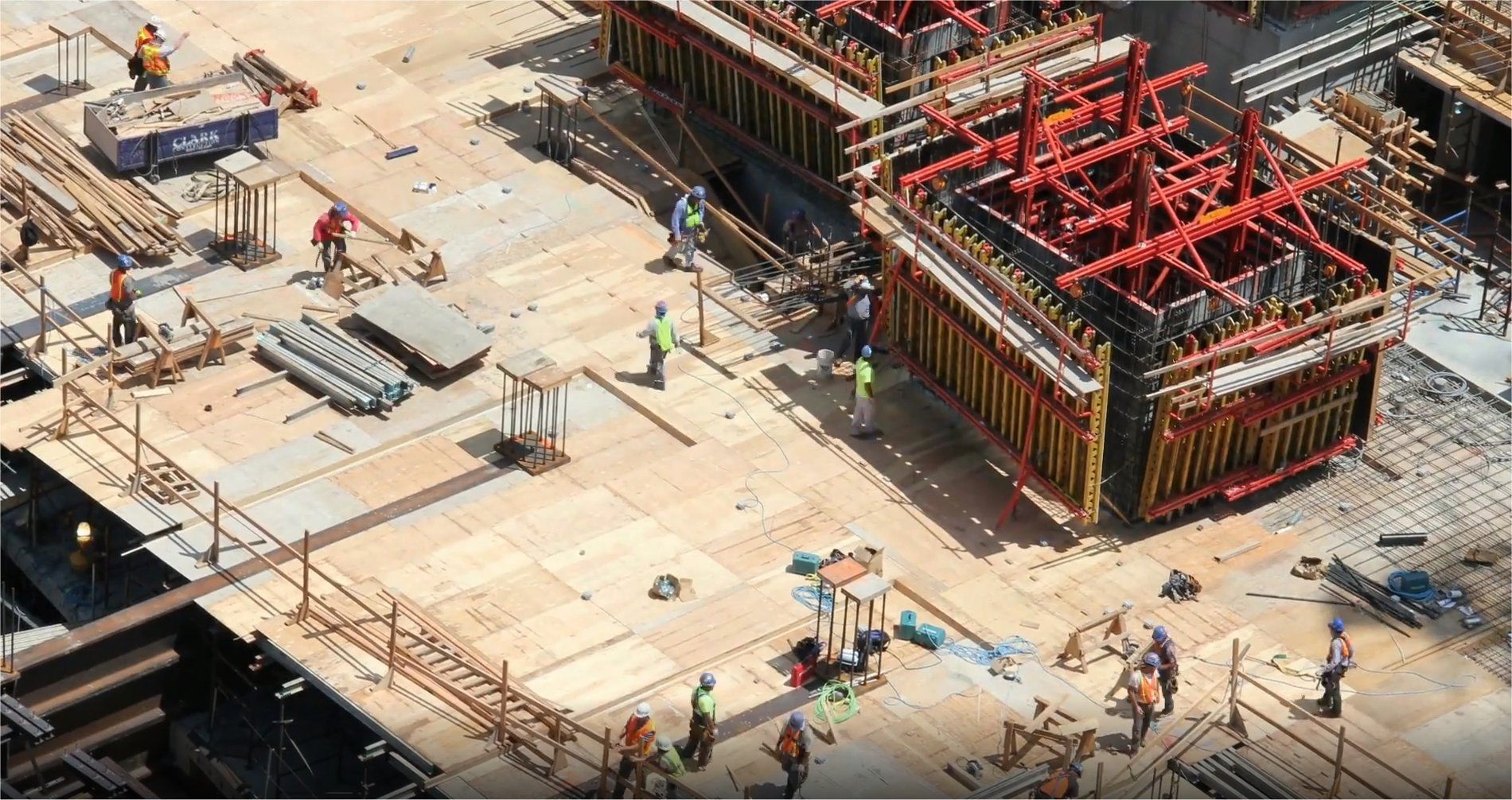
RC Slab/Wall Design
- The RC Slab / Wall Design facility now carries out comprehensive design checks to a large range of international Codes of Practice. It includes Strength/ULS and SLS checks based on flexural, twisting and in-plane effects, shear, stress limits, minimum and maximum areas of reinforcement and crack widths or spacing considerations as appropriate for all supported codes
- RC Slab / Wall modelling and design checks are now performed in a similar manner to the way that RC Frame modelling and design checks are carried out. In addition to the existing reinforcement attributes, reinforced concrete material and RC slab / wall design attributes can now be assigned to surfaces in a model that represent slabs or walls. A RC Slab / Wall Design results object is used to bring together loadcases / combinations appropriate to specific design checks and identify members for which calculations are required.
- Results can be viewed either on the model, in tabular format, or by using the print results wizard.
- Detailed rendered calculations referencing clauses from design codes are now available for all checks made for all design codes.

- In addition to existing supported codes for USA, Canada, Europe, UK, India, Australia, Singapore and China, design checks can now be carried out for: AS3600-2018 (Australia), AS5100.5-2017 (Australia), AASHTO LRFD 8th and 9th Editions (USA), ACI 318-19 and ACI 318-14 (USA), CSA C6-14 and CSA C6:19 (Canada), JTG3362-2018 (China), ELOT EN 1992-1-1 and ELOT EN 1992-2 (Greece), NZS 3101-1:2006 and NZTA Bridge Manual v3.3 (New Zealand), MOMRA Bridge Design (Saudi Arabia) and SABS 0100-1 (Ed. 2.2) (South Africa).
- A sandwich model has been introduced based upon Annex LL of EN1992-2. It divides a shell element into three layers. The outer or cover layers are considered to act as membranes resisting the direct in-plane forces along with the resolved forces from the bending and twisting moments. The central core resists transverse shearing forces only. This model has been added for AASHTO (USA), AS3600 and AS5100 (Australia), CSA-S6 (Canada), EN1992-2 and GB50010 (China). This major improvement removes most of the limitations of the currently implemented methods (Wood-Armer and Clark-Nielsen) and extends the applications for which this facility can be used.
RC Frame Design
- The RC Frame Design facility now carries out comprehensive design checks to a range of international Codes of Practice. It includes Strength/ULS checks based on biaxial bending with overall tension/compression, shear and torsion, and SLS checks for stress limits, minimum and maximum areas of reinforcement and crack widths or spacing considerations as appropriate for all supported codes, for standard and arbitrary shaped sections and prismatic or tapering members.
- In addition to existing supported codes for USA, Canada, Europe, UK, India and Australia, design checks can now be carried out for AASHTO 9th Edition (USA), ACI 318-19 (USA) and CSA S6:19 (Canada).
- The existing RC Line Reinforcement dialog has been extended to allow the specification of reinforcement for shear acting in local z and local y directions along with reinforcement considered for resistance to torsion.
Concrete Creep and Shrinkage
- The range of
concrete creep and shrinkage material models has been extended to include those for AASHTO 8th and 9th (USA), along with codes covering Europe, China and India plus both CEB-FIP Model Code 1990 and fib Model Code 2010.
Prestress
- Time dependent
prestress capabilities have been extended to include those for AASHTO 8th and 9th Edition along with codes matching the creep and shrinkage material capabilities.
Vehicle Load Optimisation
- By defining coincident effects of interest for a Direct Method Influence attribute prior to running an influence analysis, users of the Vehicle Load Optimisation facility can now obtain coincident component effects for the loads that give the most onerous main effect at locations of interest, without the need to create additional loadcases and run a static analysis.
Rail Track Analysis
- The
Rail Track Analysis software option has been enhanced to support an increased number of spans/decks and tracks, and now supports mixed decks / ballast.
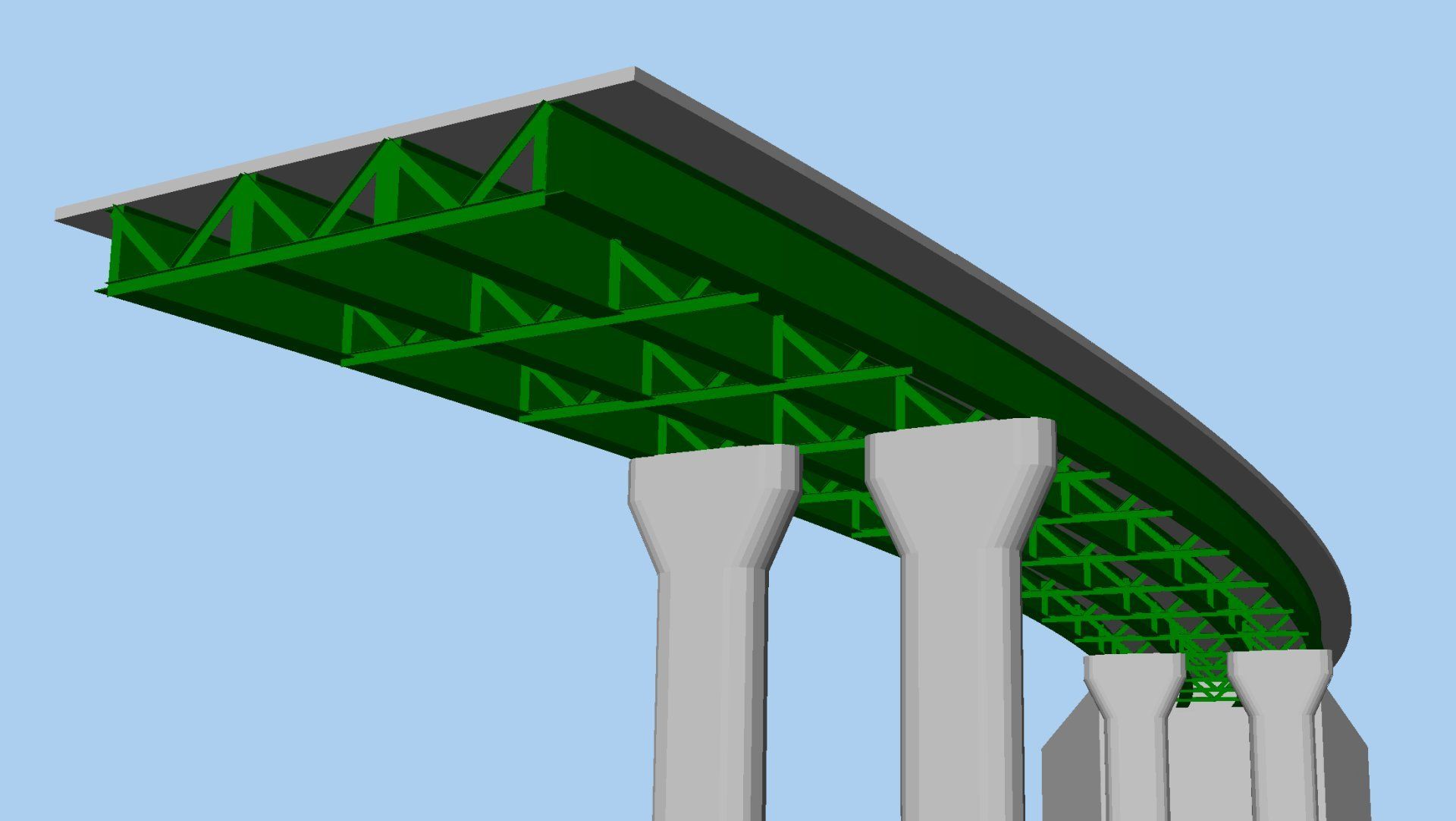
New Bridge Deck (Grillage) attributes
The range of Bridge Deck (Grillage) geometric attributes based on formulae published by Hambly (and others) has been extended to include:
- Precast section with concrete infill, comprising a slab formed of a series of sections from the section library in a row, surrounded by concrete infill.
- Transverse slab with bracing with options of Z-bracing, X-bracing, K-bracing, Lean-on, Single horizontal, and Torsional.

(continued)
- Section geometry from standard library sections/shapes can now be imported into the Arbitrary Section Property Calculator allowing, for example, a surface representing a slab to be added to a beam (or beams), or more complex section shapes to be drawn
- Previously saved LUSAS models either representing a section, or for use in defining a 2D cross-section, can be imported for use within the Arbitrary Section Property Calculator.
- Sections created in the Arbitrary Section Property Calculator can be exported as a LUSAS model.
- When opening pre-version 20 models, user-defined standard and arbitrary sections referenced by a geometric beam attribute are automatically converted into model utilities and will appear in the Utilities Treeview when a model is loaded.
- When opening pre-version 20 models, user-defined standard and arbitrary sections referenced by a geometric beam attribute are automatically converted into model utilities and will appear in the Utilities Treeview when a model is loaded.
- A new import sections facility allows for importing selected sections from any legacy sections.csv file into the current model. Sections are listed according to section type with check boxes to allow selection of any / all sections to be imported into the Utilities Treeview.
- A new plate section property calculator calculates properties for a range of riveted or welded section types, either with reference to sections held in the main section library or from user-defined values.
- The Precast section menu item has been removed from the Section Property Calculator menu list. Precast sections (without a top slab) are now available in the section library. Precast beam sections with a top slab can now be created by using the Bridge Deck (Grillage) section property calculators or, if required, the updated Arbitrary Section Property Calculator.
Bridge temperature and shrinkage profiles to design codes
- In addition to existing supported codes for AASHTO, Australian and Europe, temperature profile loading to design codes now includes CSA S6-06, S6-14 and S6:19 (Canada) , JTG D60: 2004 and 2015 (China), IRC 6 - 2017 (India), SP/M/022 Third Edition (Amendment 3, 2018) (New Zealand), TMH 7 (South Africa), and BD37/01 and CS 454 Revision 0 (UK)
- Bridge deck shrinkage loading now includes AASHTO 9th (USA) and CSA S6-14 and S6:19 (Canada)
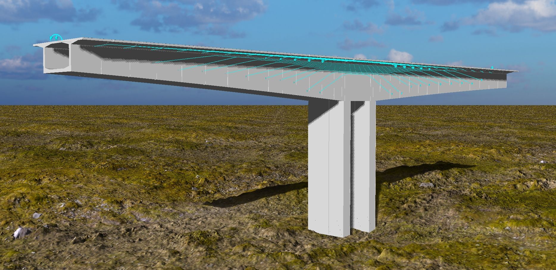
Pile-soil interaction modelling
- A new Embedded pile material layup attribute provides the means to specify the soil around an embedded pile in terms of strata, p-y curve data and associated settings. P-y curves can also be created using the Utilities > P-y Curve menu item. As in industry, the term "p-y curve" is used as a shorthand meaning to incorporate p-y curves, t-z curves and Q-z curves. P-y curves can be defined for a library of soil materials, namely: API RP2A-WSD, DNV-OS-J101, ISO 19902:2007 or JTS 167-4-2012.
- A new material model (model 49) has been introduced for use by the embedded pile material layup which allows the modelling of load history. Resultant lateral force-displacement and vertical force-displacement curves describe the deformation of the pile.
- The existing piecewise linear elastic joint model dialog now includes a 'Cylindrical' check box (for the no rotational stiffness joint type), which provides the option to set force/displacement curves in both vertical and radial directions, instead of in three Cartesian axes.
Improved joint and interface assignment
- The insertion of joints or interface elements has been simplified and automated for specific situations. Joints can now be inserted by assigning a joint mesh to features that form the boundary to neighbouring features. This improved method of inserting joints automatically creates the required additional nodes and inserts joint elements at nodal locations at, along or across a selected feature in the case of points, lines or surfaces. Assignment can be made to a selection of many single features simultaneously.

- Point, line and surface features can now be 'grounded' via joints, whereby relevant support conditions are applied to the free node of the joint element(s) automatically.
- The offset distance at which a joint symbol is drawn away from the actual joint location can now be specified.
- The previous 'manual' method of inserting joints has been retained for legacy purposes and for cases not covered by the new 'automatic' method.
Enhanced membrane behaviour
- The implementation of corotational formulation for large deformation of membrane elements now allows these elements to be used in linear buckling and nonlinear static and dynamic analysis involving large deformation. This allows membrane elements to be used in form-finding for tensile fabric structures, for example.
Evaluation version
- An evaluation version of LUSAS is now available, requiring registration in order to use an online evaluation licence.
User interface enhancements
- User-controlled transparency has been introduced providing clearer and more detailed visual feedback when modelling and viewing results. Transparency is supported on a per-layer basis for each view window and also allows for individual transparency settings for specific geometric attributes in the Attributes Treeview.
- Updated Attributes Treeview icons show the status of any defined, assigned or transparent attribute settings including using individual icons for point, line, surface and volume based assignments.

- Improved default contour appearance. The contour properties dialog has been updated with the 'Contour Display', 'Contour Range' and 'Seed Colours' tabs now replaced by one 'Appearance' tab that provides access to most of the settings from the removed tabs. In addition, five contour 'styles' can be used as supplied or be customised to plot contours for different uses in order to suit project needs.
- Two new results components “Stress" and “Strain" are provided for shell elements. These allow viewing contours consistently with other results, with the results to be drawn over the whole "fleshed region" of each element.
User change requests
The originators of all requested changes to the software that have been incorporated in this release will be notified individually.
- Re-ordering of Attributes and Utilities treeview items. Attributes (and utilities) can now be clicked and dragged up and down their respective treeviews. As with loadcases that already support this ability, ID numbers are updated to suit. In order to force an attribute to be in first place, it is necessary to drag it on top of its parent item. Note that reordering is not permitted when attributes are being viewed in alphabetic order.
- Renumbering of Attributes and Utilities treeview items. It is now possible to renumber any group of attributes (and utilities) by right-clicking on the appropriate folder name and choosing 'Renumber'. Right-clicking on the Attributes/Utilities folders or in the white space beneath their respective treeviews allows for renumbering of all attributes within each parent folder/entry from the same specified value.
- Filtering of Attributes and Utilities Treeview data is now possible by selecting either 'None', 'Geometric', 'Material', 'Supports', 'Loading' or 'All' from the panel at the foot of those treeviews. As implemented initially for the for the Analyses treeview, this automatically “closes up” parent folders of all tree branches, and “opens up” only the desired ones, effectively hiding entries and reducing clutter. A 'Specify' button can be used to create more complex permutations – e.g. a selection of 'Loading' and 'Supports'.
- 'Mirror (screen)' option added to the 'Copy' dialog. This allows users to choose which of the four extremities of the selection (left, right, top, bottom, in screen axes) to use as the mirror plane. An extra radio button allows the further choice of mirroring about a selected / specified mirror line.

- New 'Threshold' option on the Values properties dialog. This enables labelling of values above a specified value. Two new edit boxes for minimum and maximum thresholds, are provided which are dependent on the existing “maxima” and “minima” choices.
- Easy stepping through loadcases. The current active loadcase name is now stated beneath the Analyses Treeview. Adjacent 'Plus' and 'Minus' buttons, when chosen, set active the next and previous loadcase within each Analysis in the Analyses Treeview, allowing stepping through a series of loadcases to easily view modelling stages or results.
- Reduction of error and warning messages output. The number of errors and warning messages from Solver written to the Modeller text output window has been reduced to a maximum of 5 errors and 25 warnings.
- Filtering of text output. Text output messages can now be filtered according to type (error, warning, errors and warnings, etc.) by selection of an appropriate radio button at the top of the text output window and, for ease of viewing, symbols have been added to denote the type of message produced.
- IDs of constituent loads are now shown in the Compound Load dialog box.
- A checkbox option 'Skip mesh' has been added to the 'File open' dialog to omit loading the mesh when a model is loaded. This will allow for faster loading of large models, if wanting to just check some geometric information or detail, or to load a model successfully if the mesh has somehow become corrupted.
- Loadcase definitions
can now be viewed within Combinations and Envelope listings. A new 'View' button has been added to every dialog where it is possible to include some loadcases from an 'Available' list into an 'Included' list, as seen on combination and envelope definitions and animation load history dialogs. For a selected item in the 'Available' panel, pressing this button opens up the definition dialog for the item to act as a reminder of the definition. Where the selected loadcase is a combination or envelope, the definition dialog will have the same 'View' button, allowing recursive viewing of the loadcases used in each higher definition.
General
Other user change requests
User manuals
New worked examples
- Joint Modelling for an RC Bridge with a Drop-in Span
- Defining p-y Curves for a Piled Integral Bridge
- Simple grillage analysis
- Simple Building Slab Design
- Rail Track-Structure Interaction with Offset Bearings and Train Loading Groups