Version 23 new features and enhancements
In addition to many useful new facilities and improvements, Version 23 provides pushover analysis, a fibre-reinforced concrete material model, two new geotechnical models and access to more customisation and scripting capabilities.
In detail...
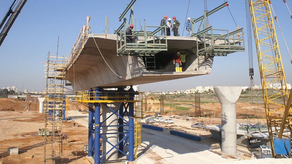
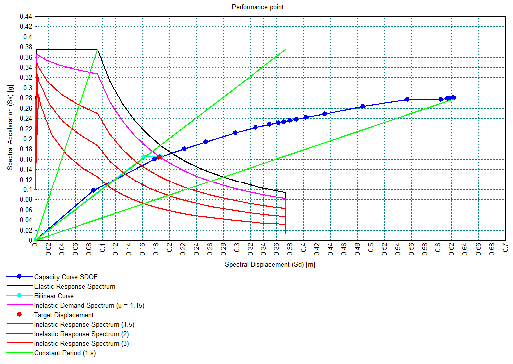
Pushover analysis
- For a pushover analysis the new pushover curve facility will extract the pushover curve from which the ‘performance point’ or ‘target displacement’ can be derived for a supported Code of Practice.
- Related new facilities are provided for defining plastic hinges, plotting contours of hinge status for Immediate Occupancy, Life Safety and Collapse Prevention categories, and for inspecting force-deformation curves for specific hinges.
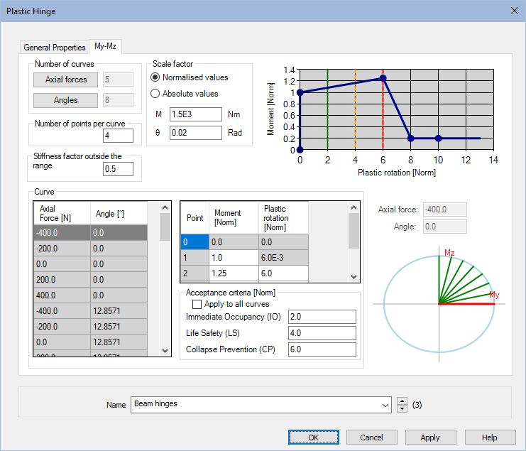
Plastic hinges
- The existing range of interacting and non-interacting hinges has been enhanced for use in pushover analysis. Any number of points can be used to define force-deformation curves. Automatic force-displacement definitions have been included for steel sections. For other materials (e.g. concrete sections), moment-rotations may be computed and introduced manually as absolute values.
Plot contours of plastic hinge status
- Plot contours and values of plastic hinge status for Immediate Occupancy, Life Safety and Collapse Prevention categories.
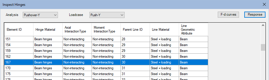
Inspect Hinges
- The inspect hinges tool allows you to view he definition of hinges and create new hinge materials by editing existing ones. It shows the actual (absolute values) of the force-deformation curves. If results are available, the response of a specific hinge for a chosen analysis and loadcase can also be inspected.
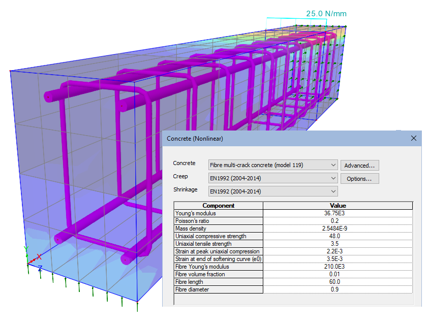
Fibre multi-crack concrete model
- A Fibre Multi-Crack Concrete material model is now supported. This is a plastic-damage-contact model in which damage planes form according to a principal stress criterion and then develop as embedded rough contact planes.
- The model can be combined with the creep and shrinkage behaviour appropriate to any of the supported Codes of Practice, resulting in a comprehensive time-dependent behaviour including cracking and crushing.
Direct export to MS Excel
Calculated results may now be exported directly to a Microsoft Excel spreadsheet .xlsx file rather than having to be viewed within the Print Results Wizard first. This can be done in three ways:
- From the Print Results Wizard dialog by checking the 'Save to file' checkbox.
- By right clicking on a ‘Print Results Wizard’ attribute within the Utilities treeview and selecting the context menu item 'Save To Excel File'.
- If using the LUSAS Programmable Interface, call the LPI function saveToFile, and provide an optional argument for the location and filename.

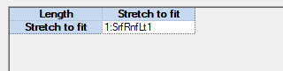
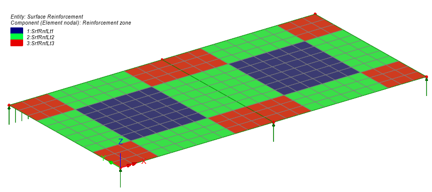
Reinforcement attributes and zones in surfaces
Reinforcement in the top and bottom of a slab or in the faces of a wall is now termed 'surface reinforcement' in LUSAS and is stored as an attribute within the Attributes treeview. Bar reinforcement size, spacing, cover and skew angle of bars can be defined according to project requirements. Cartesian and radial reinforcement arrangements are supported as well as the ability to define extents over which a defined reinforcement layout applies.
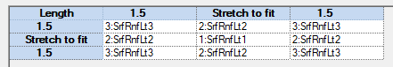
- The reinforcement attributes created are subsequently assigned to each surface representing a slab or wall for which the reinforcement layout is applicable. RC slab/wall design attributes need also to be assigned to the appropriate surfaces representing concrete slabs and walls to allow RC Slab/Wall Design calculations to be carried out. Visualisation of x and y reinforcement directions is now provided.
- The extents of any defined reinforcement zones may be visualised by accessing the properties dialog of the contour layer and choosing to plot results for 'Reinforcement (model)'. Each selected reinforcement layout assignment / zone will be displayed in a unique colour alongside an associated contour key.
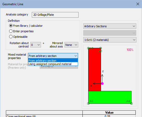
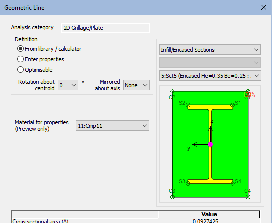
Mixed material modelling
- For arbitrary sections, where section properties are dependent on the modular ratios of component materials, these now have the option to be calculated at tabulation time using the material an Arbitrary Section Material attribute assigned along with the geometric attribute. The use of several Arbitrary Section Material Attributes means the section properties can be updated to reflect in-construction and in-service conditions, avoiding the need to define multiple arbitrary sections or re-run the arbitrary section property calculator for each material combination.
- Infill/Encased sections now use the compound material from the assignment for each element and in each loadcase rather than be specified in the geometric attribute. This is now consistent with Bridge Deck (Grillage) material. Different material properties may be assigned in different analyses and loadcases as required to model staged construction processes.
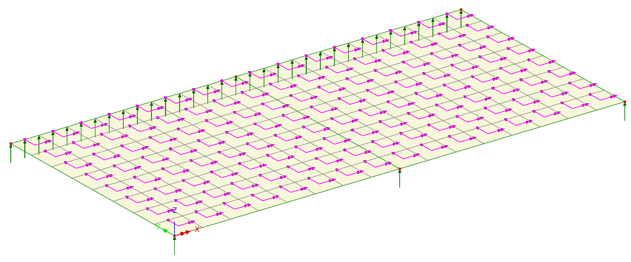
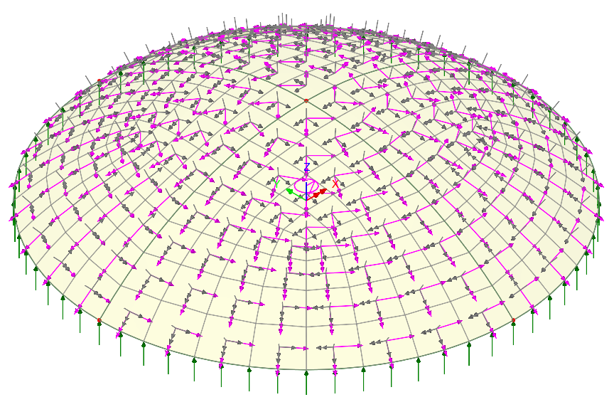
Improved visualisation of loading
- Loading can be visualised by its effect on the model or by definition, allowing you to see exactly how the loading is applied. This is particularly useful with discrete loads showing clearly where loading intersects a search area and where loading that misses the search area will not load the model.
- Loading values are now displayed alongside loading arrows, but overlapping labels are suppressed to ensure that the highest magnitude is always legible values visible. In situations where overlapping occurs, higher results values take priority over lower ones and larger negative values take priority over lesser ones. Labels that overlap are made transparent, suppressing the associated arrows, providing clearer displays. Zooming in to enlarge the view of a model will progressively make previously overlapping arrows and load values fully visible.
- Labelling of loading with magnitude and units makes it easier to check the loading assigned and to distinguish between force and pressure.
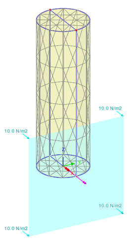
Visualised by definition
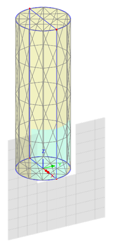
Visualised by effect on model
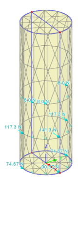
Visualised by effect on mesh
(uses different loading)
Vehicle Load Optimisation now supports EN1991-2 LM2 loading
- Group 1b is now available on the Vehicle Load Optimisation Optional Code Settings dialog for Load Model 2. This is for local verifications ("short structural members" to EN1991-2 clause 4.3.1(2)(b)). ψ and beta adjustment factors can be modified using the Advanced options button.
Specify initial element temperatures in a thermal analysis
- Initial temperature loading conditions can now be specified for a thermal analysis in a manner that is consistent with a hygro-thermal analysis.
Concrete creep and shrinkage to NZS 3101
- Design code 'NZS 3101:2006 – New Zealand Standard – Concrete Structures Standard' is now supported.
Time dependent tendon losses for NZS 3101
- Tendon loss calculations (friction, anchorage set) and post-installations losses (elastic shortening, creep and shrinkage of concrete and relaxation of tendon steel) based on time inputs and calculated stresses are now supported for NZS 3101.
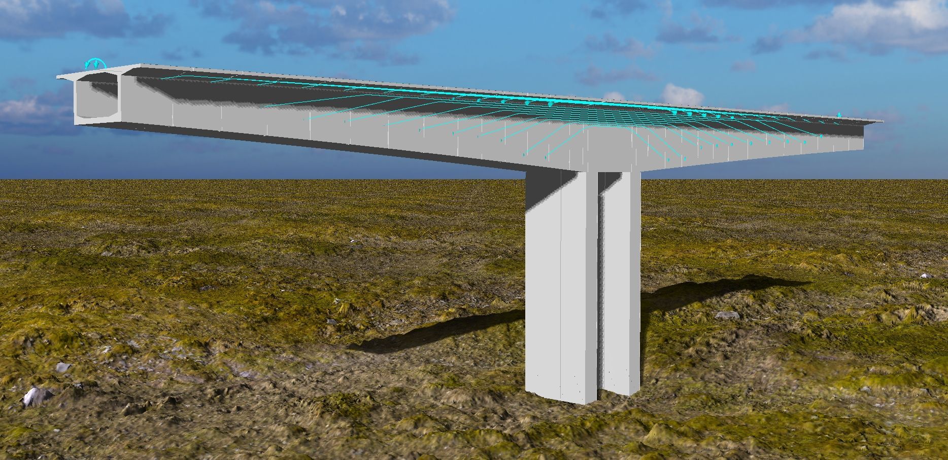
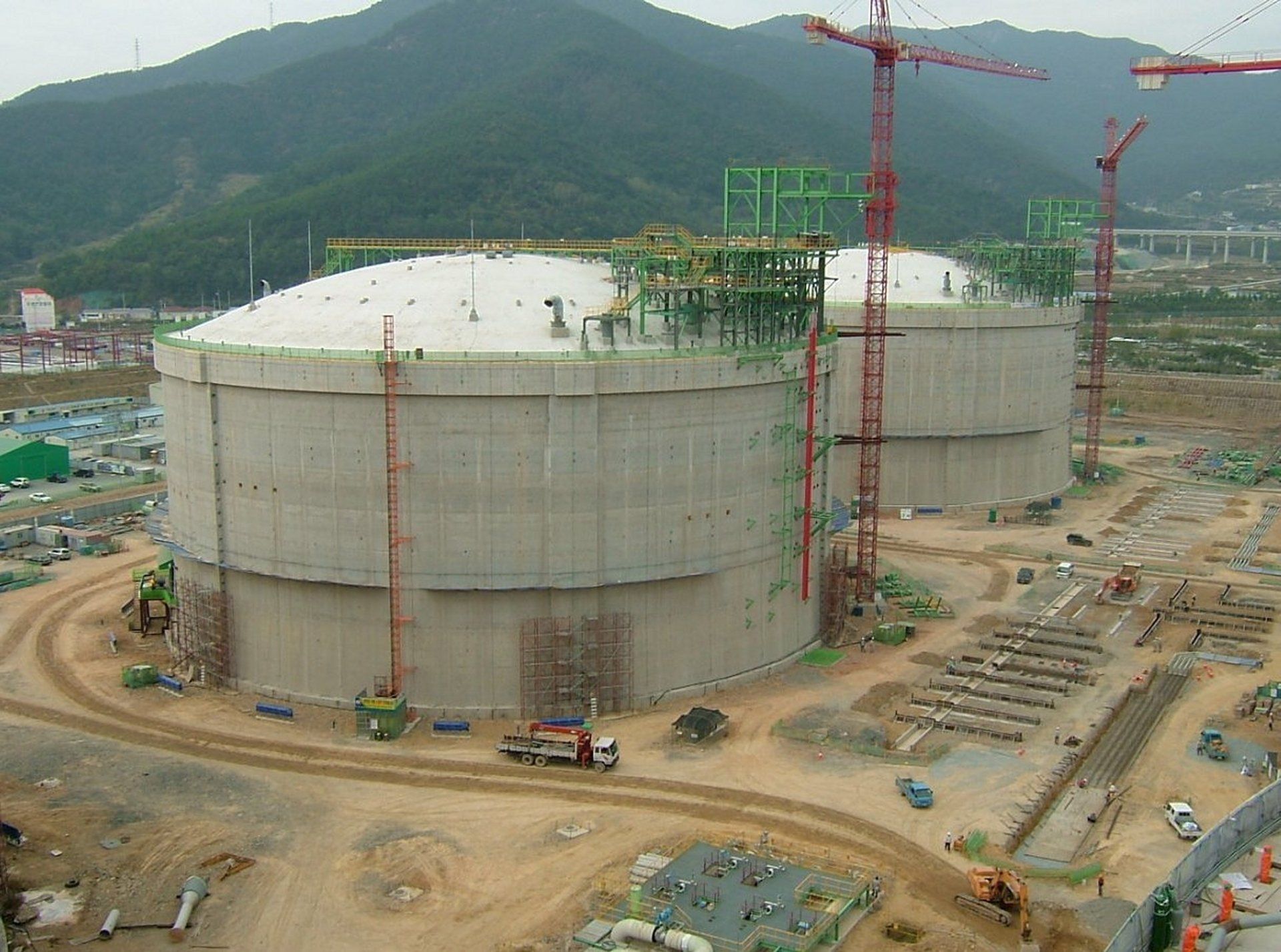
LUSAS Tank Updates
A 'Concrete (Membrane)' tank option is now available in the concrete tank definition dialog for structural and seismic modelling and assessment. This tank type assumes the liquid is retained by a membrane that transfers all loads directly to the outer concrete wall, with no structural independence of the inner layer.
- Horizontal beam stick models now support the distribution of liquid masses following the guidelines of ASCE 4-16:2017.
- Vertical beam stick models have been revised to clearly define masses of different components instead of lumping all the masses at each level. The inner tank (when present), the flexible liquid mass, and the rigid liquid mass are now independently modelled and connected to the main structure through a horizontal rigid beam, while horizontal displacements are restricted.
- The 'Add Seismic Loading' dialog has been updated to support concrete membrane tank types. The liquid induced moments are now optionally automatically calculated, along with the heights of lumped liquid masses (impulsive and convective).
- For all types of tank definition, a context menu option 'Show Properties' is now available. This allows for easy inspection of useful tank information such as average dimensions, cross sectional areas, volumes, total structural and non-structural masses, total insulation thicknesses and seismic design natural periods, stiffnesses and dimensions.
See LUSAS Tank for more details about this software product.
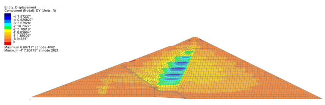
Hardening soil model
- The hardening soil model with small strain is a multi-surface plasticity model based on the well-known Duncan-Chang hyperbolic model. The hardening soil model is capable of modelling a variety of granular and cohesive soils. Its parameters are obtained directly from standard triaxial and oedometer laboratory tests. An overview example is provided with this release. See the Geotechnical Analysis option for details of all models supported.
Barcelona Basic Model
- The Barcelona Basic Model is a constitutive model for unsaturated soils which reduces to the Modified Cam Clay model at zero suction. The key feature of the model is a load collapse curve, which allows an increase in yield stress (apparent pre-consolidation stress) with suction and introduces the possibility of expansion or collapse upon wetting depending on the current pressure. See the Geotechnical Analysis option for details of all models supported.
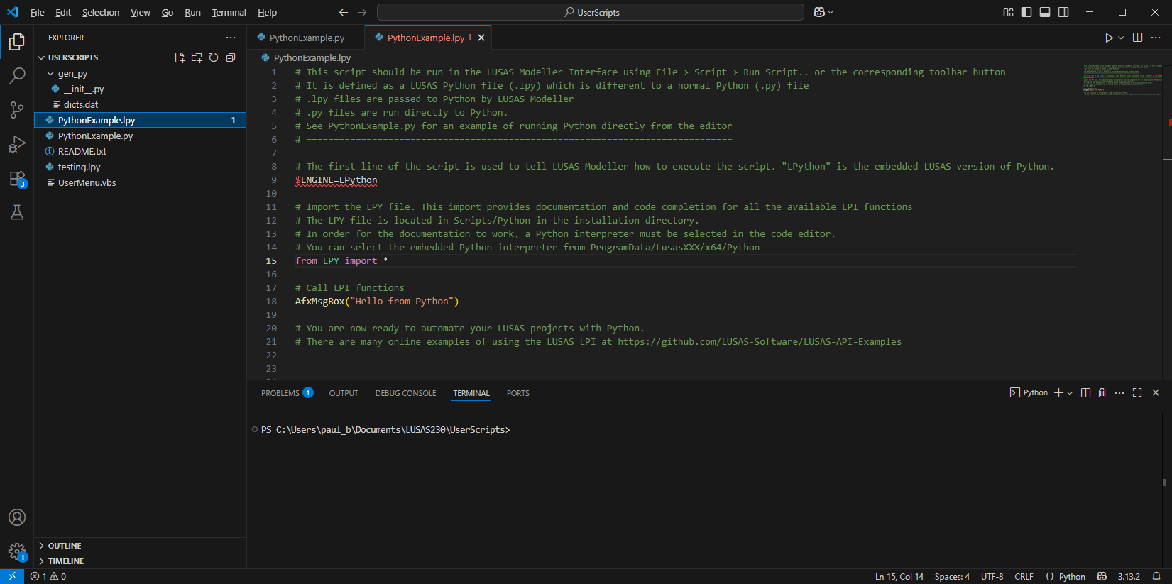
Smart LPI text editor with Intellisense and improved help
- Links are provided during the LUSAS installation process to optionally install VSCode - the LUSAS recommended editor for LPI script files. If not installed during installation, selecting the menu item File > Script > LPI Editor from within Modeller, or by using the LPI editor toolbar button will initially take you to a download page and then, after installation, will subsequently launch VSCode as the LPI editor.
- VSCode includes a debugger and language servers capable of providing 'IntelliSense' (a code completion tool that provides a range of features to assist users in finding the correct LUSAS function and understand its arguments) and a huge library of extension modules.
LUSAS GitHub repository
- Introduced between the releases of V22.0 and V23.0, the LUSAS GitHub repository provides practical examples of using the LUSAS Programming Interface (LPI) in Python, VBScript, Jupyter, C#, VB.Net and Grasshopper.
- The repository provides engineers with a centralised, well-documented set of automation examples using the LUSAS Programming Interface (LPI) and encourages the use of LUSAS in digital workflows (e.g., BIM, Python-based engineering, AI-assisted design) by lowering the learning curve.
See the LUSAS GitHub repository for more details.

New Grasshopper plugin components
- Point, Activate/deactivate, Volume member, Volume mesh, Loadcase, and Re-order loadcase components have been introduced into the LUSAS plugin for Grasshopper since the release of V22.0 and V23.0.

Python now supplied as part of a LUSAS installation
- An embedded Python interpreter is now provided as part of the LUSAS installation.
- It can be used to run Python scripts from LUSAS and, when 'Python' is selected as the script language in the LUSAS configuration utility it will be used to generate session files and display LPI commands in the Python language.
See LUSAS Programmable Interface (LPI) Scripts for more information
Specify behaviour of variations outside evaluation limits
- For general field, surface function and profile variations, it is now possible to specify the behaviour of a variation outside of its defined limits.
User manuals
- Relevant documentation has been updated for this new release.
- Selected manuals are provided in PDF format as part of the LUSAS installation and are also available for download from the LUSAS website.
Worked examples
Worked examples (in PDF format) and associated files referenced by those examples are available for download from the User Area of the LUSAS website. New for this release are:
- Pushover analysis of a steel frame.
- Construction modelling of Oroville Dam using the hardening soil model.