Steel Composite Bridge Wizard
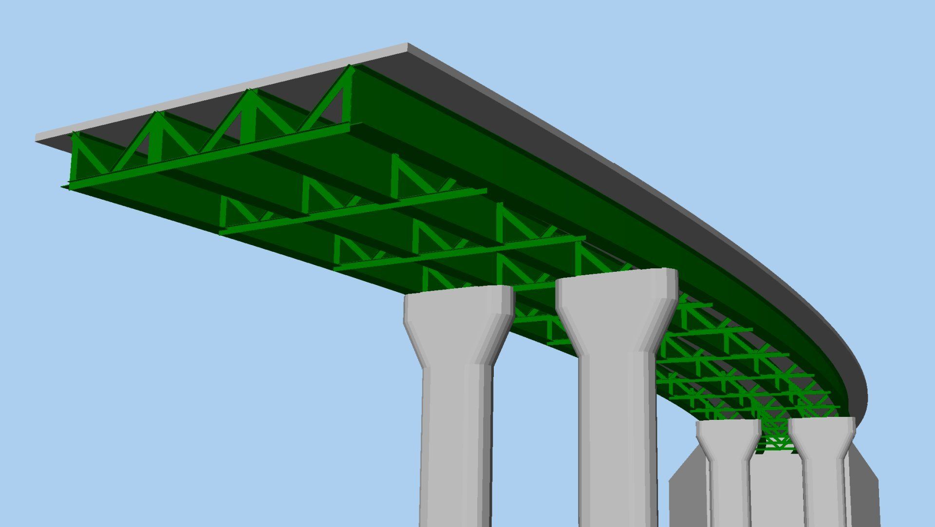
Use for quick and easy generation of the deck model geometry and corresponding mesh, geometric, material, support and local coordinate data for slab-on-beam composite I-girder bridges.
Define models that accommodate:
- Straight or curved decks of constant radius.
- An arbitrary skew, where a skew can additionally be set per support and interpolated across the spans.
- Any number of spans and supports.
- Square and skew bracing.
- Transverse stiffeners.
- Design utilities for design checking against supported design code
Watch the 60 second feature video.
In detail...
Define girder sections
Define cross-sectional information for a composite girder and slab (without upstands) for all required locations on the structure.
Visualise the section being built in real-time as slab, top flange, web, and bottom flange dimensional data is entered.
Once defined, the composite I-Girder sections are used to define Girders.

Define girders
Define positions along the nominal bridge centreline at which pre-defined or newly created slab and girder cross-sections apply for a girder.
The length(s) over which section assignments are made for girders either side of the control centreline is calculated by the bridge wizard.
Once defined, the girder components are used to define spans.

Define spans
Define the girders present in each span along with any bracing runs that occur between girders. Girders with offset slabs may be mirrored to create symmetrical arrangements.
Once defined, spans are used to define a bridge model as a whole.

Define supports
Define supports for the girders that are present in each span along with any bracing that occurs between girders at these supports.
Skew can be defined uniquely for each support, and independently at that support for any defined support bracing.
Once defined, the supports are used in the definition of the bridge model as a whole.

Define whole bridge
Define the type of bridge (straight or curved) to be generated along with a minimum mesh size.
Spans defining the bridge are selected (or defined) along with stating a length over which they apply. An option to reverse a span is also provided. Supports at the end of each span also need to be stated.
Once defined, the model can be automatically generated by the wizard.

Additional information relating to transverse stiffeners, bracing assemblies and intermediate bracing runs may also be specified either during the use of the wizard, or afterwards to update the initially created model.
Watch a longer video...
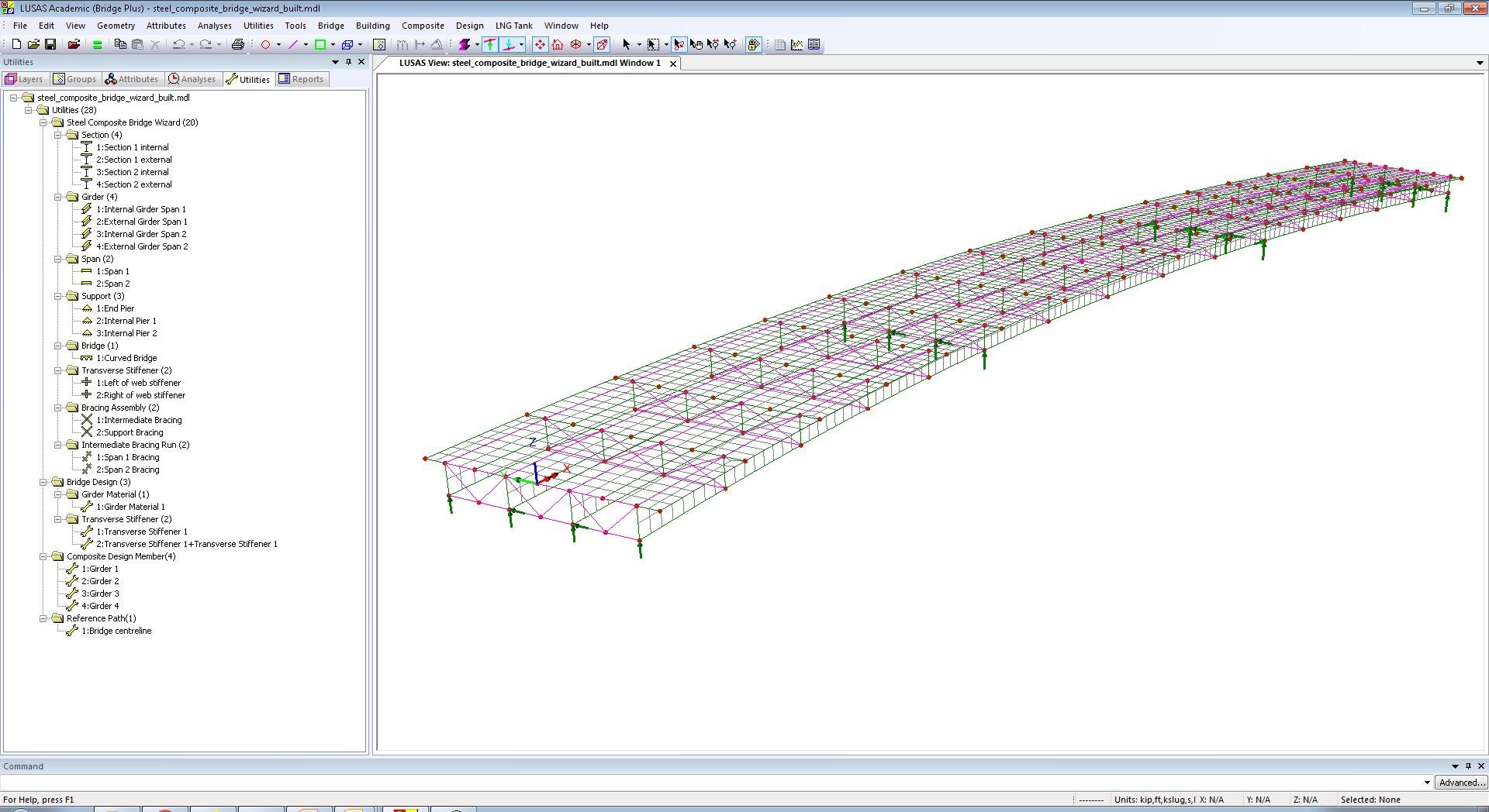
Shows how to create a beam and shell model of a 3-span curved steel composite bridge using the Steel Composite Bridge Wizard.
Composite sections, girders, spans, supports are defined prior to generating an initial bridge model from the input data.
Stiffeners and cross-bracing details are added also using the wizard and the bridge is re-generated to show their inclusion in the model.
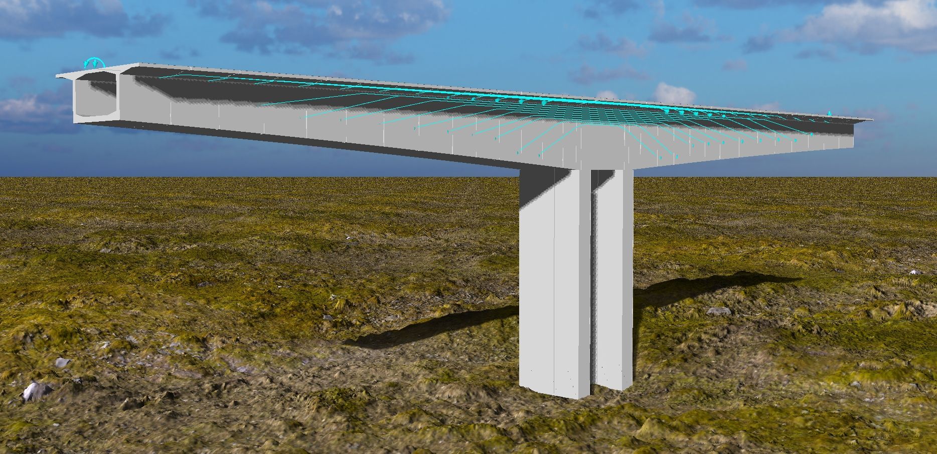
After solving the model, bending moment results are displayed for a selected girder by using the slice resultants facility.
(Version 19.0)
In Version 21...
Learn more about...


For more information...
- For more details of LUSAS software products visit www.lusas.com
- To download LUSAS software visit the LUSAS User Area of the main website.
- Contact us via our contact form, or use Live chat, if available.