Version 19.1 new features and enhancements
Recent developments in LUSAS have enhanced our ability to deliver a single advanced solution for any infrastructure project. LUSAS version 19.1 extends these capabilities even further, supports more design codes, and in summary includes:
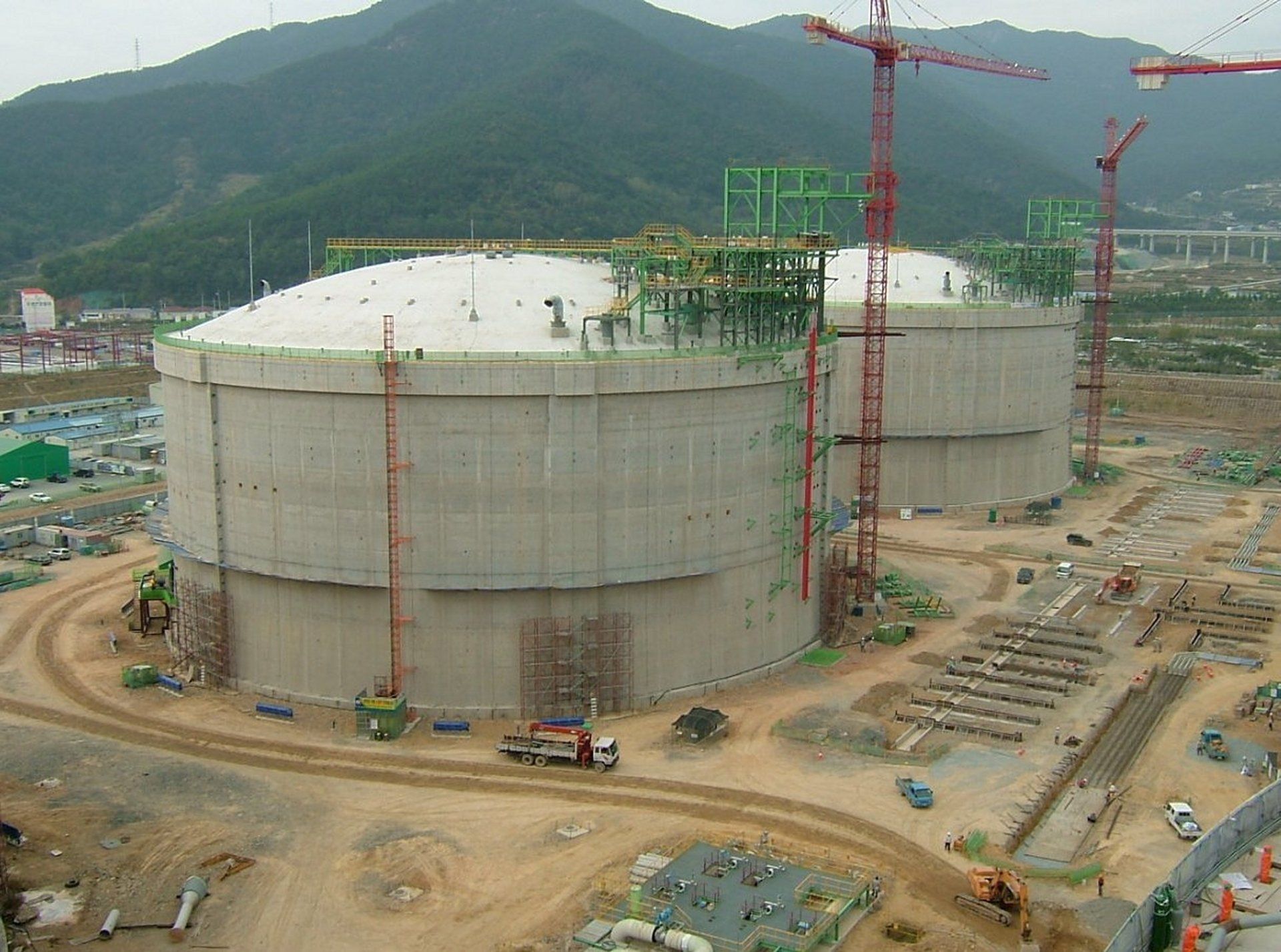
New product: LNG Tank Analysis and Design System
LNG Tank Analysis and Design System
The 'LUSAS LNG Tank Analysis and Design System' is a licensed software product that allows engineers to automatically create a range of 2D and 3D finite element models of full containment circular tanks from user-defined parameters. Using these models, a range of analyses can be performed, and optional design checks carried out for specified load combinations and supported design codes.


Other enhancements
Steel Frame Design
The Steel Frame Design software option has been extended to include design checks for BS5400-3:2000
Concrete Creep and Shrinkage
- The range of concrete creep and shrinkage material models has been extended to include those for Chinese code JTG 3362-2018 and fib Model Code 2010.
- For Codes of Practice that include suitable clauses, material properties and creep/shrinkage behaviours can be adjusted according to a prevailing temperature during the service life of the structure. This includes CEB-FIP Model Code 1990, fib Model Code 2010, and JTG 3362-2018.
- The age of structural elements at the time of their activation can now be calculated with adjustment for temperature during curing.
Prestress
- Time dependent prestress capabilities have been extended to include those for Chinese code JTG 3362-2018 and fib Model Code 2010.
Vehicle Load Optimisation
- The Vehicle Load Optimisation facility has been extended to support more bridge assessment codes and now includes optimised loading and custom vehicles for United States of America AASHTO MBE Section 6A (LRFR) and United Kingdom CS 458 rev 0 with ALL Model 1.
RC Frame Design
- RC Frame design now allows the direction of the neutral axis to be defined for uniaxial bending as part of defining the RC design attributes for all supported design codes.
Design combinations
- The Design combinations facility, which assigns LUSAS loadcases, envelopes or basic combinations to predefined load types for a supported design code), now supports CS 454, IRC: 6-2017, EN1990 for Railway Bridges and Footbridges - for Recommended Values and Irish, and UK National Annexes, and EN1990 for Highways Bridges and Footbridges for the Italian National Annex.
- The design combinations implementation for Highway Bridges for EN1990 for Recommended Values, Irish, and UK National Annexes has been extended to include 'Persistent Combination Set C'.
Cursor-based box selections
- A right-to-left definition of box extents can be optionally set to select all features crossed by the selection box (as often used by CAD software), rather than include only those items wholly inside the selection box.
Thick beam warping
- For thick beams that support warping, torsional end conditions can now be defined.
LUSAS Teaching and Training version limits increased
- The Teaching and Training version of LUSAS, which restricts the size of model that can be solved, now has the following increased limits:
| Nodes | Points | Elements | Degrees of freedom | Loadcases |
|---|---|---|---|---|
| 1000 | 200 | 500 | 3000 | 20 |
File export
- Export of LUSAS model data to a Visual Basic Script file is now provided.
Improved exporting of results data for use by the Composite Deck Designer (PontiEC4)
- Exporting of results can now be used with 2D grillage or 3D analysis models made from beams, shells, or a combination of those element types.
- Composite Design Member details are now used when exporting force and moment results data for use in carrying out design checks by the Composite Deck Designer (PontiEC4) software option. As a consequence, beam/shell slice resultants can now also be exported.
For more information see Composite Bridge Deck Design (PontiEC4)
Associated model data
- The 'Associated Model Data' folder, that holds files created in the course of a building a model and running an analysis, is now named 'LusasFiles32' for a 32-bit installation.
- The previous ability to specify alternative locations of files that are created in the course of building a model and running the various analyses associated with it, as specified via the LUSAS configuration utility, has been removed.
Restricted 64-bit LUSAS Modeller (Beta)
- Version 19.1 offers a new restricted 64-bit beta version of Modeller that should only be used if advised to do so by LUSAS Technical Support. Users are recommended to keep using 32-bit Modeller as geometry cannot be edited in this beta version.
Version 19.0 new features and enhancements
New Bridge Wizard
Steel Composite Bridge Wizard
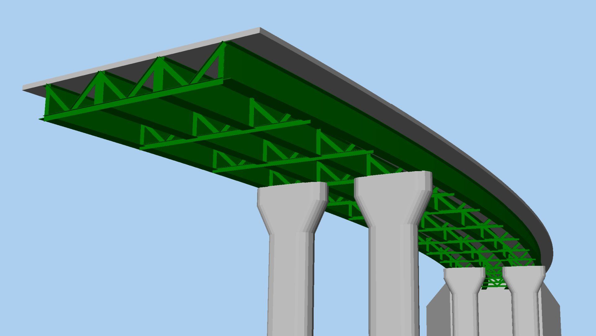
The Steel Composite Bridge Wizard generates the model geometry and corresponding mesh, geometric, material, support and local coordinate attributes for models of slab-on-beam composite I-girder bridges where the slab and web are modelled with shell elements and the top and bottom flanges, web stiffeners and bracing are modelled using beam elements.
Models can be defined that accommodate:
- Straight or curved decks of constant radius.
- An arbitrary skew, where a skew can additionally be set per support and interpolated across the spans.
- Any number of spans and supports.
- Square and skew bracing.
- Transverse stiffeners.
- Design utilities for design checking against supported design codes.
Example of a curved multi-span steel composite bridge deck with bracing created by the wizardNew Paragraph
Design-related improvements
Composite Bridge Deck Design
The Composite Bridge Deck Design software option provides a consistent approach to design, regardless of the analysis approach adopted, using slice resultants to calculate design forces. This allows an analysis model to be created without having to define design details initially. It allows for the complexity of the analysis model to be increased without changing the design data, and also permits a number of changes to be made to the design information to see what the effect of a particular change would be, without having to change or solve the analysis model each time.
The following steps are required to carry out a composite bridge deck design check:
- Create a model of the bridge deck by using the Steel Composite Bridge Wizard, or by using the grillage wizard, or by manually creating an appropriate model, and solve it to obtain results.
- Define a composite bridge deck design member for each girder (simple spans) or series of girders (continuous spans) of interest in the model.
- Specify the design code to be used by selecting the Design> Composite Deck Design menu item.
- Define a results utility This identifies the design members for which calculations are required and brings together the loadcases / combinations appropriate to the various limit state checks.
- View the results in tabular format, and optionally add selected results to a model report.


The following design code is currently supported:
- AASHTO LRFD 8th Edition. (USA) - AASHTO LRFD Bridge Design Specifications 8th edition, American Association of State Highway and Transportation Officials 2017.

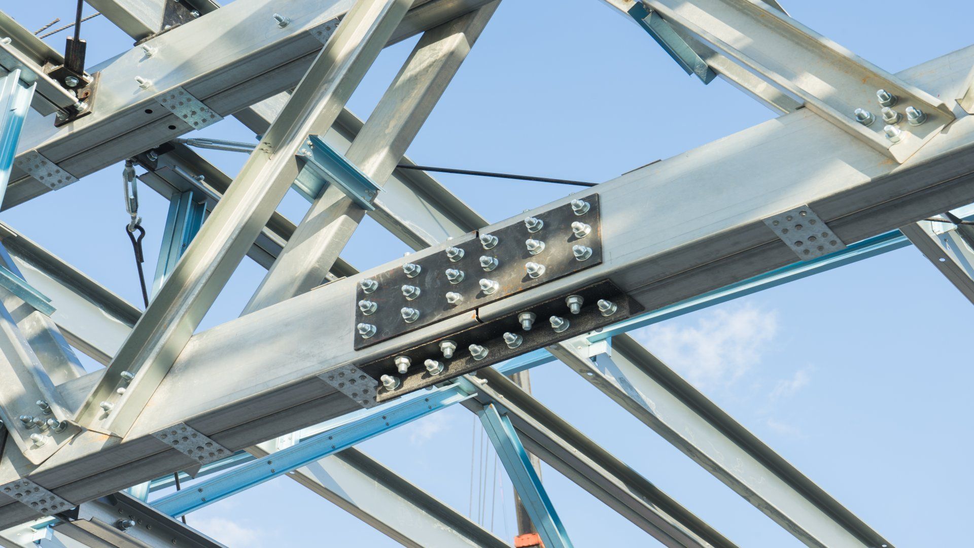
Steel Frame Design improvements
- ANSI/AISC 360-16 Specification for Structural Steel Buildings, American Institute of Steel Construction, Chicago, July 2016
- GB50017-2017 Standard for design of steel structures, China Architecture & Building Press, China.
Reinforced Concrete Frame Design improvements
- AASHTO 8th Ed. (USA)
- AS5100.5-2017 (Australia)
- CSA S6-14 (Canada)
- IRC:112-2011 (India)
Reinforced Concrete Slab/Wall Design improvements
- GB 50010-2010 - Code for design of concrete structures, China Architecture & Building Press, Beijing.
Vehicle Load Optimisation improvements
- India IRC:6-2017
Standard Specifications and Code of Practice for Road Bridges - Section : II - Loads and Stresses (7th Revision) Indian Roads Congress, New Delhi.
Geotechnical / Soil-Structure Interaction
Phi-c reduction
Phi-c reduction attributes can now be defined and assigned to a model to assess soil stability and safety factors for soil that is represented by Mohr-Coulomb or Hoek-Brown material models. Attributes can be assigned to all or just some of the relevant features in a model, allowing the safety of a particular slope (for example) in a large analysis to be evaluated without other parts of the model being affected. Assignment is made to a particular loadcase or analysis stage, which defines the applicable loading, boundary conditions and activation status.
By its very nature, a phi-c reduction analysis will always run until solution failure, so it is best used in branched analyses where it can be used to study safety factors at several stages of construction without terminating the solution

Hoek-Brown material model
The Hoek-Brown model is now supported. This is an elastic-perfectly-plastic constitutive model suitable for the modelling of rock failure. It is an empirical model, and its parameters are based on both laboratory test data, and visual observation of the rock. The model can be used with standard continuum elements as well as the two-phase elements.
Drained and undrained conditions
Drained and Undrained attributes can be defined from the Attributes > Pore Water Pressures... menu item. They are used to define regions of a model where the soil is drained or undrained.
Drained and undrained attributes can be assigned to features representing soil that are meshed with two phase elements and modelled with two-phase materials in both 2D or 3D models. The use of such attributes is a conceptual shortcut from the beginning to the end of a consolidation analysis, representing the extreme undrained and drained conditions.
Additional K0 models
Two additional K0 initialisation options, 'Wroth' and 'OCR sin(phi)', have been added to the Modified Cam Clay material model to allow initial stresses in soil to be calculated.
Modelling improvements
Bridge Deck (Grillage) attributes introduced
Bridge Deck (Grillage) geometric attributes have been introduced to define geometric properties of specific types of bridge decks that are analysed with reference to, or derived from grillage formulae published by Hambly and others.
When assigned to a model along with a new Bridge Deck (Grillage) material attribute, which contains separate material definitions for the slab, girders, slab and reinforcement (for cracked sections) that are defined in the relevant Bridge Deck (Grillage) geometric attribute, users can more easily analyse the different phases of construction of these types of bridge decks with one model by the use of the multiple analysis facility. In short, one set of grillage geometric attributes is suitable for the life of a bridge, as the sections do not change, whereas several material attributes may be needed to represent the in-construction, short term, and long term cases.

Bridge deck temperature and shrinkage profile loading
Bridge deck temperature profile loading can be defined for the following design codes.
- AASHTO 8th
- AS 5100.2:2017
- EN1991-1-5:2003 Approach 1
- EN1991-1-5:2003 Approach 2
Bridge deck shrinkage profile loading currently supports:
- AASHTO 8th
General variation of temperature or strain through-section
For general use, a temperature/strain profile loading can be defined by stating the temperature of the top of the section followed by defining a series of segment thicknesses and corresponding values for the specific height at which the expression is being evaluated. Segment thicknesses and temperature/strain may be stated as a single value, or as expressions, making it possible to replicate expressions in bridge industry Codes of Practice and define code-specific profiles that are not currently supported elsewhere in LUSAS.
Defined profiles can be visualised for a stated visualisation height. The same profile may be assigned to multiple geometric sections of differing heights.


Generate influences from beam/shell resultants and inspection locations
Direct Method Influences can now be generated from beam/shell slice resultant locations and at inspection locations. Direct Method Influence attributes can be assigned to pre-defined Inspection locations, or to Beam/Shell Slices using the 'Assign to' context menu item for the DMI attribute, and then selecting the inspection points or beam/shell slices to which the assignment should be made on the Influence Assignment dialog that subsequently appears.
The ability to assign DMI attributes to Beam/Shell Slices now makes it possible to use the Vehicle Load optimisation facility on bridge decks idealised using mixed beam and shell elements.
Model view "Orientation cube" introduced
An orientation cube can now be optionally displayed in each model view window. This provides visual feedback on the orientation of a model, and rotates and updates as the model is rotated or orientated. The top of the cube is aligned to the defined vertical axis for the model.

The orientation cube has labelled faces with default names of Left, Right, Bottom, Top, Back and Front, and edges and corners that highlight when a cursor is moved over them. Selecting a face, edge or corner of the cube will orientate the model to be viewed from the selected direction. The model can also be dynamically rotated by clicking and dragging to rotate the orientation cube.
Home, Dynamic Rotation, Resize, and Perspective buttons can be optionally added beneath the axis cube for easy selection.
Analysis enhancements / updates
Analysis branches introduced
Analysis branches may be added to the Analyses Treeview by selecting the New > Branch context menu item for any loadcase in the Analyses Treeview that has (or inherits) a nonlinear or transient control. They allow the creation and solution of one or more sub-analyses to investigate the response of the model at a particular loadcase or "stage".
Examples of use include:
- Carrying out a linear moving load analysis of construction equipment during each stage of the construction of a segmental bridge deck,
- Performing an eigenvalue natural frequency analysis or a buckling analysis during construction.
- Performing a phi-c reduction analysis to derive safety factors for a geotechnical model from each stage in an excavation process.
- Performing an earthquake analysis where gravity is applied in a static nonlinear step, then the earthquake is run as a transient branch. Several sample earthquakes may be run in each branch.
Any number of sub-analyses may be defined for a single parent loadcase.

Access to Fastest available and Frontal Solvers provided
The Fast Multi-frontal solver is now made available by default to new clients.
Two Solver-related radio buttons previously included at the bottom of the 'Model properties' dialog have been replaced with a droplist control on the dialog that additionally allows specifying solution options on the 'Solve Now' dialog. These now allow for solving by the fastest available and appropriate solver for the task in hand, or the frontal solver, which provides more error diagnostics should issues arise. An option to only solve for the first loadcase (for quick model attribute assignment checking purposes) is also included.


Direct method Influence analysis improvements
Direct Method Influence analysis is now faster because the Solver results file is now generated at the same time as the stress recovery stage, saving significant processing time.
Larger Direct Method Influence analyses can now be carried out with either a finer grid or a finer mesh without manually setting any additional parameters. The analysis is split into batches that make maximum utilisation of the memory available but which ensure that no matter how large the DMI analysis, it will solve successfully.
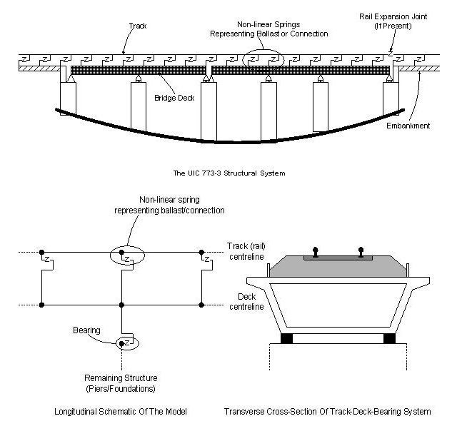
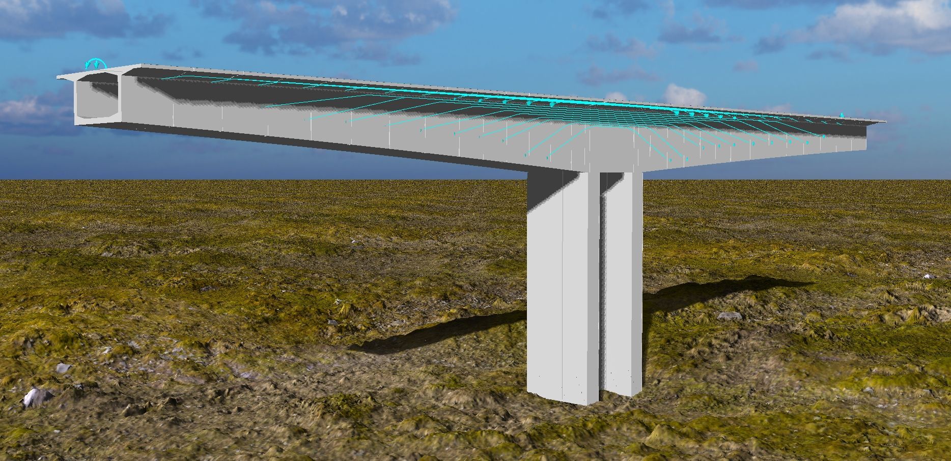
Rail Track Analysis enhancements
The LUSAS Rail Track Analysis software option now includes the following new features / enhancements:
- Bearings can now be modelled offset (inboard) from the ends of the decks.
- Multiple Train Loading Groups can be analysed within the same analysis.
- Avoidance of stubby elements in the modelling.
- Improved pier modelling.
- Train loads are allowed to be outside the extents of the model, allowing long trains to be passed over structures without having to have excessively large embankments to model the correct arrival and departure of the trainset from the structure.
- Use it for EuroCode nomenclature of Traction loads (instead of Acceleration).
- Significant speed up of train/rail load definition and assignment.
- Section axes for deck and pier now included in the Geometric Properties worksheet.
- Improved results / chart titles in the tabulated output.
Results enhancements
Slice resultants improvements
Once defined, slice sections are now visualised immediately on the model without the need for a solve to have taken place first.
Results averaging speed-up
Averaging of element results across discontinuities has been made more efficient, reducing the time it takes to display averaged results in this situation.
General
Other user change requests
User manuals
New worked examples
- Steel Composite Bridge Wizard - shows how to use the wizard to build a 3-span bridge.
- Staged construction modelling of a 3-span bridge deck - models the construction and loading phases of a 3-span bridge
- Composite bridge deck design to AASHTO 8th edition - shows use of the new composite bridge deck design software option.
- Slope stability modelling showing Phi-c reduction - shows use of branched analyses and the new Phi-c attribute.
- Simple grillage analysis - shows use of the new bridge deck grillage attributes.
- Grillage load optimisation - shows use of the new bridge deck grillage attributes on a model with optimised vehicle loading.
In Version 21...
Learn more about...


For more information...
- For more details of LUSAS software products visit www.lusas.com
- To download LUSAS software visit the LUSAS User Area of the main website.
- Contact us via our contact form, or use Live chat, if available.